
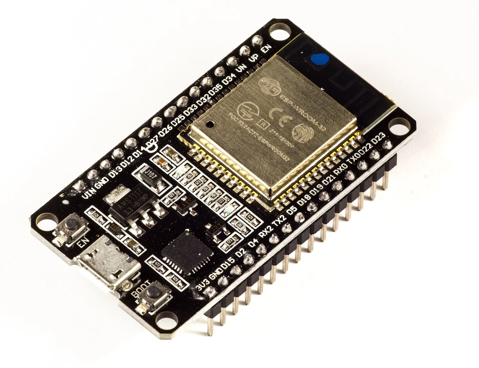
An ESP32 node with a MAX30102 sensor measures heart rate and oxygen saturation and publishes the readings over MQTT in a few lines of code, yet the Analog Devices datasheet for the MAX30102 states plainly that the part “is not presently an FDA-approved product” and should not be used for diagnostic purposes. It is the same component that turns up in dozens of “DIY pulse oximeter” tutorials. The distance between that tutorial and something a clinician could use to decide on treatment is almost entirely regulatory and procedural, not a matter of code.
Context
With maker electronics, assembling a telemonitoring chain is trivial. An ESP32 (Wi-Fi and Bluetooth on board, under £10) reads an I2C sensor, connects to an MQTT broker and ships samples to a backend. The PubSubClient library on Arduino, an Eclipse Mosquitto broker and a Python consumer using paho-mqtt close the loop in an evening. MQTT is a published standard: OASIS released it as MQTT 3.1.1 in 2014 and it was adopted as ISO/IEC 20922:2016. For power draw, reconnection and hierarchical topics it suits fleets of low-cost nodes.
That ease is real and useful at the prototyping stage. The trouble starts when the prototype is presented — or worse, used — as though it produced a trustworthy clinical reading.
The regulatory problem
In Europe, software or a device intended for a medical purpose falls under Regulation (EU) 2017/745 (the MDR). A medical purpose covers the diagnosis, prevention, monitoring, prediction and prognosis of a disease. The Medical Device Coordination Group’s MDCG 2019-11 guidance sets out how to qualify and classify software: if the stated intended use is to provide information used to take decisions for a diagnostic or therapeutic purpose, that software is a medical device, whether it runs on dedicated hardware or on an £8 microcontroller.
The point many maker projects skip is that what drives the classification is the stated intended use, not the technology. An ESP32 showing a number on a display “for demonstration” is unregulated. The same ESP32 sending that number to a platform where a nurse sets an alarm threshold has a monitoring purpose, and from there you need a technical file, risk management (ISO 14971), a software life cycle (IEC 62304) and, for the electrical part applied to the patient, conformity with IEC 60601-1.
Architecture, and where it breaks
The typical chain remains:
[ESP32 + MAX30102] --MQTT/TLS--> [Mosquitto] --> [Python consumer] --> [storage + UI]For healthcare use the weak points are not in the transport. MQTT over TLS with QoS 1 gives acceptable delivery guarantees and encryption. The problems sit at the two ends.
On the sensor side, the MAX30102 is a two-wavelength photoplethysmograph: it reads a waveform, not a calibrated SpO2 figure. Deriving a clinically meaningful saturation percentage from it requires a calibration curve validated on real subjects, across different perfusion states and skin pigmentations, plus signal-quality gating that discards samples corrupted by motion or poor contact. The datasheet itself warns that the reading is affected by placement, movement and ambient light. Without that validation, the number published to MQTT is a bench artefact.
On the system side, failure handling is almost always missing. What happens when the node enters deep sleep (the ESP32 drops below 10 µA, handy for battery life) and misses samples? What happens if the broker is unreachable and a retained message shows an old value as though it were current? In an industrial setting a missing or stale reading is a nuisance. In patient monitoring it is a hazard, and IEC 60601-1 formalises this through essential performance: the performance whose loss beyond a threshold creates an unacceptable risk.
The critical point
Between industrial and healthcare use of the very same hardware, what changes is not signal quality but the consequence of an error. An MPU6050 watching a motor’s vibration can get an FFT wrong: a maintenance alarm is lost, an extra downtime is scheduled. The same MPU6050 used for fall detection on an elderly person, if it gets a prediction wrong, produces a false negative on a real fall, or a false positive that erodes trust in the system until it is ignored.
This is why the two domains diverge early, despite starting from the same bill of materials. In industry you optimise cost per node and mechanical robustness. In healthcare the dominant constraint becomes traceability of the decision: every value shown must be traceable to a calibrated sensor, a versioned firmware, a chain of custody for the data. This is not paperwork bolted on afterwards; it is what separates a measurement from a numerical opinion.
Implications for prototyping
In healthcare too the Arduino/ESP32 prototype keeps real value, provided it is called what it is: a tool for validating a product hypothesis, a data pipeline, an ergonomic flow. It answers questions like “can the patient place the sensor without help?” or “is the latency from reading to dashboard acceptable?”. These are honest questions a £15 node answers well.
It becomes dangerous when whoever watches the demo credits it with the reliability of a certified device. The temptation is strong because the number on the display looks the same. The discipline lies in keeping the separation explicit: the proof of concept measures the feasibility of the flow, not the physiological quantity. Moving to a device requires sensing with declared and validated accuracy, compliant electrical isolation, documented risk management and, where the purpose is medical, CE marking under the MDR.
Limits
The above concerns European regulatory qualification and consumer-grade optical sensors; it does not cover cases where a component ships already CE-marked as a medical device, nor the specifics of in-vitro diagnostics (Regulation (EU) 2017/746). The ESP32 current figures quoted refer to the bare chip: a development board with an LDO regulator and a USB-serial bridge draws orders of magnitude more, a detail that changes the battery-life arithmetic in a wearable.
- https://www.analog.com/media/en/technical-documentation/data-sheets/max30102.pdf
- https://docs.oasis-open.org/mqtt/mqtt/v3.1.1/os/mqtt-v3.1.1-os.html
- https://www.iso.org/standard/69466.html
- https://health.ec.europa.eu/system/files/2020-09/md_mdcg_2019_11_guidance_en_0.pdf
- https://eur-lex.europa.eu/eli/reg/2017/745/oj
- https://www.espressif.com/sites/default/files/documentation/esp32_datasheet_en.pdf
- https://mosquitto.org/
- https://www.noze.it/en/insights/arduino-iot-sanita-industria/
Cover image: Espressif ESP32 ESP-WROOM-32 development board with male pin headers on both sides, top-down view on a neutral background — photo by Ubahnverleih, CC0 — https://commons.wikimedia.org/wiki/File:ESP32_Espressif_ESP-WROOM-32_Dev_Board.jpg